A few months ago, I posted about my LED Cube, which was a 4x4x4 grid of 64 LEDs. Since then, I’ve built a version that’s 8 times as large and twice as dense in each dimension, an 8x8x8 cube:
It has 512 LEDs, four separate signal cables coming from a single microcontroller, and 1824 solder joints. The spacing between LEDs is 2cm (compared to the 4x4x4’s 4cm) meaning that the whole thing is around 16cm to a side. From when I got all of the LEDs to when I finished it, it took around 3 months to make, however the actual time spent working on it was probably in the range of around 100 to 200 hours.
It runs on the same server software stack as the 4x4x4, but with a different microcontroller to download the cube states and display them (which requires some different timing logic, and different signal sending code to write to all four signal lines at once). My git repository is here: https://github.com/abryant/LED-Cube.
Most of this post is some fairly detailed instructions about how to build it / how I built it, with some extra information about how it’s controlled at the end.
Building the Cube
The cube is built of 8 layers, each of which is 8 strips, each of which contains 8 LEDs.
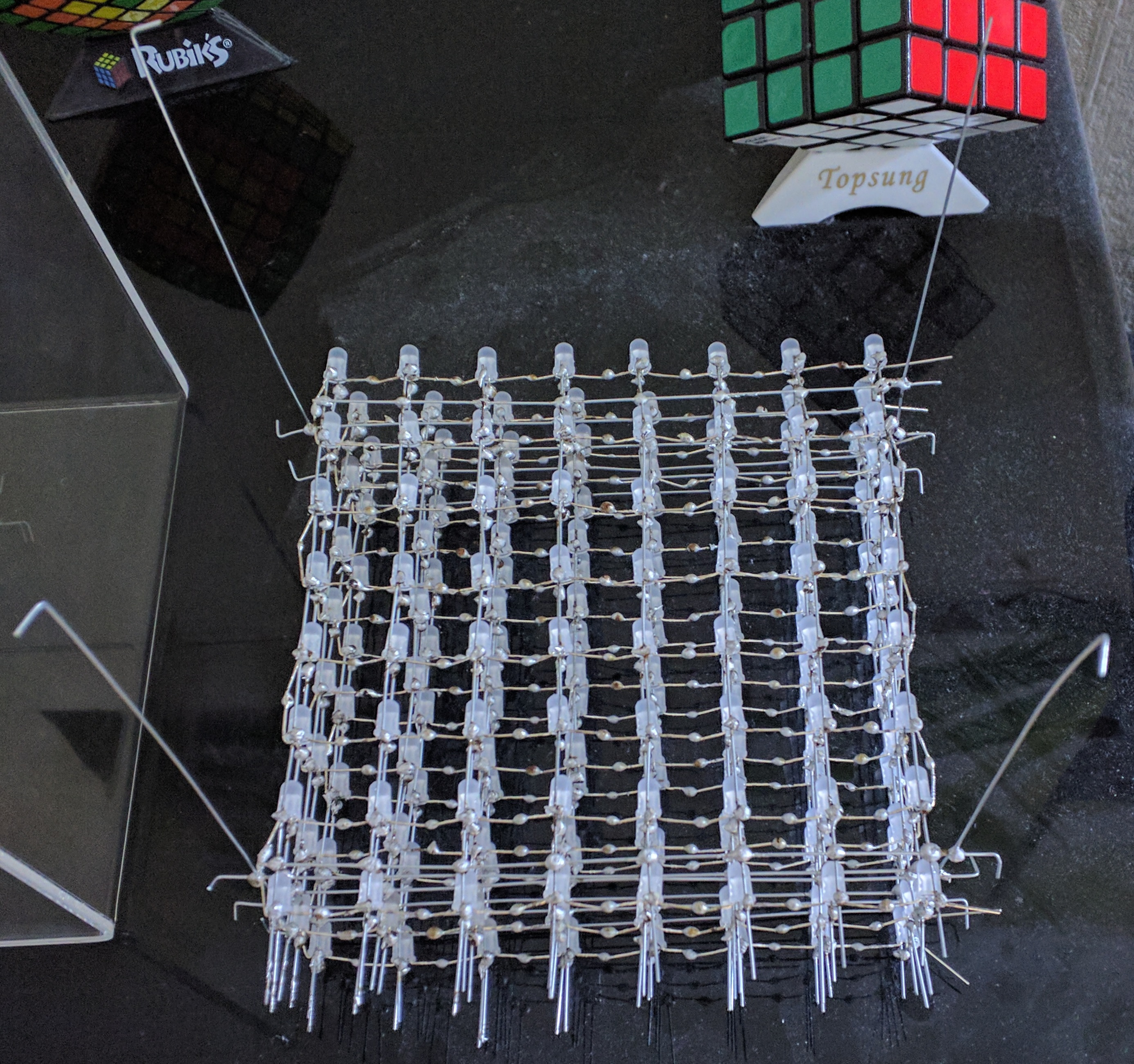
A strip
Each LED has four wires: Data out, GND, +5V, Data in, in that order. The first thing to do is connect all of the LEDs to a power supply, which also serves as the structure holding them up. I used a block of polystyrene (which came with the soldering iron) to hold the LEDs in place, with one of the pins of each LED sticking straight down into it:
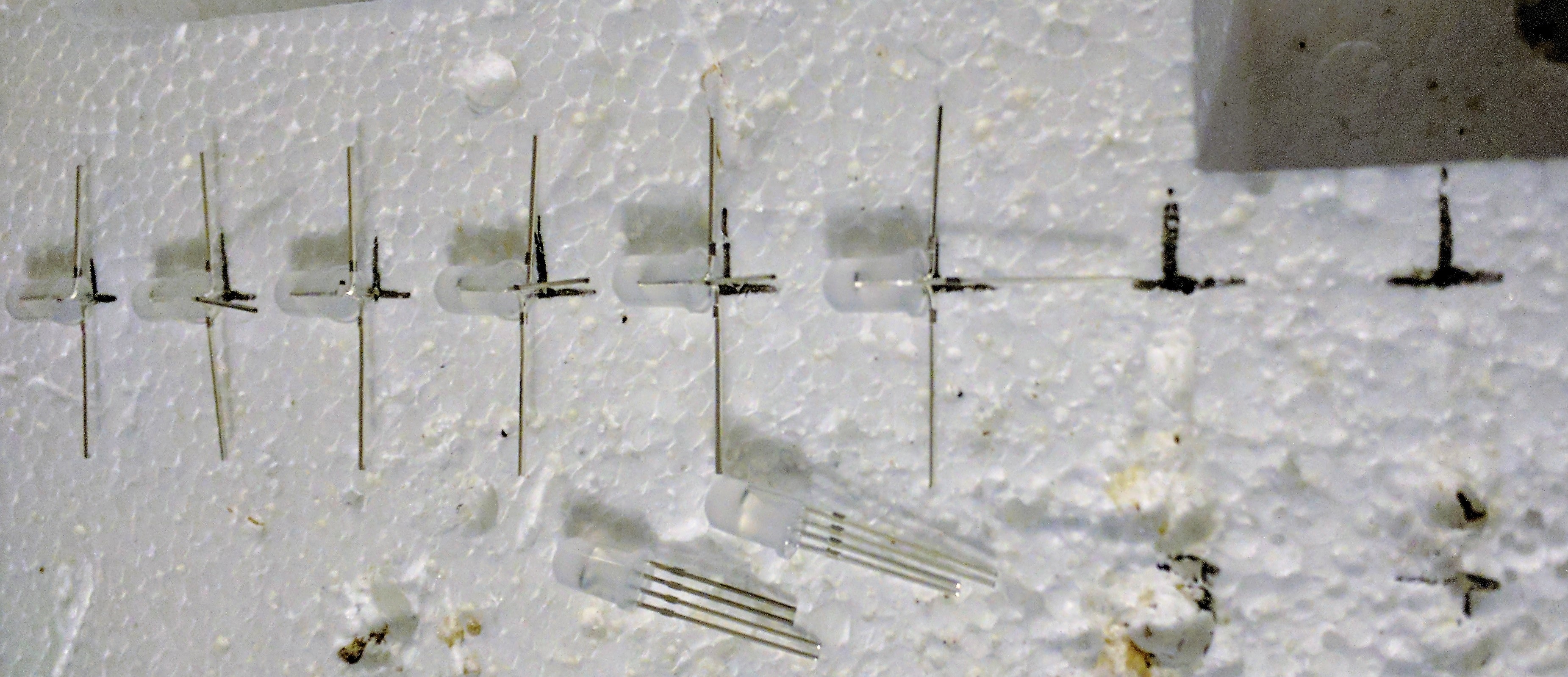
Here, the longer ground wires are along the bottom, the shorter +5V wires are along the top, and the data pins go up/down in alternating directions (more on that later). The marks are where the last two LEDs needed to go. Next, we need to solder the rails on the +5V and GND lines, which involves straightening the wire. For this, I am using 22 gauge galvanized steel wire:
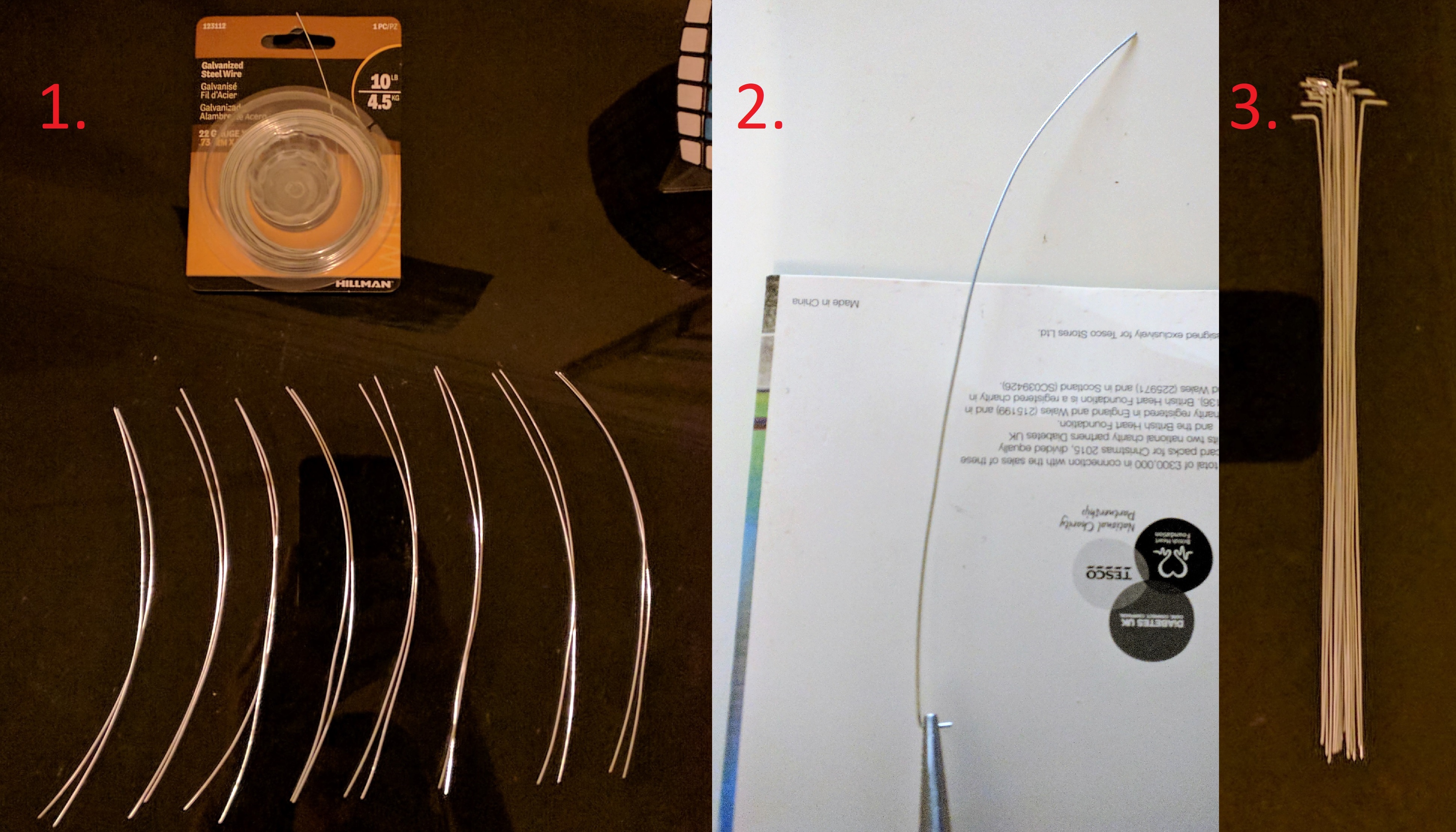
- Cut the wire to length from the reel. This requires two 16cm pieces of wire for a single strip, or 16 pieces for all of the strips in a layer.
- Straighten the wire by putting it between two pieces of card (I used a greetings card I had lying around), and pressing down on the card while pulling the wire through with some pliers.
- Finish straightening the whole set. The 90 degree bend at the end of the wire is partly for pulling it through the card with the pliers, and partly to secure it to the polystyrene while soldering.
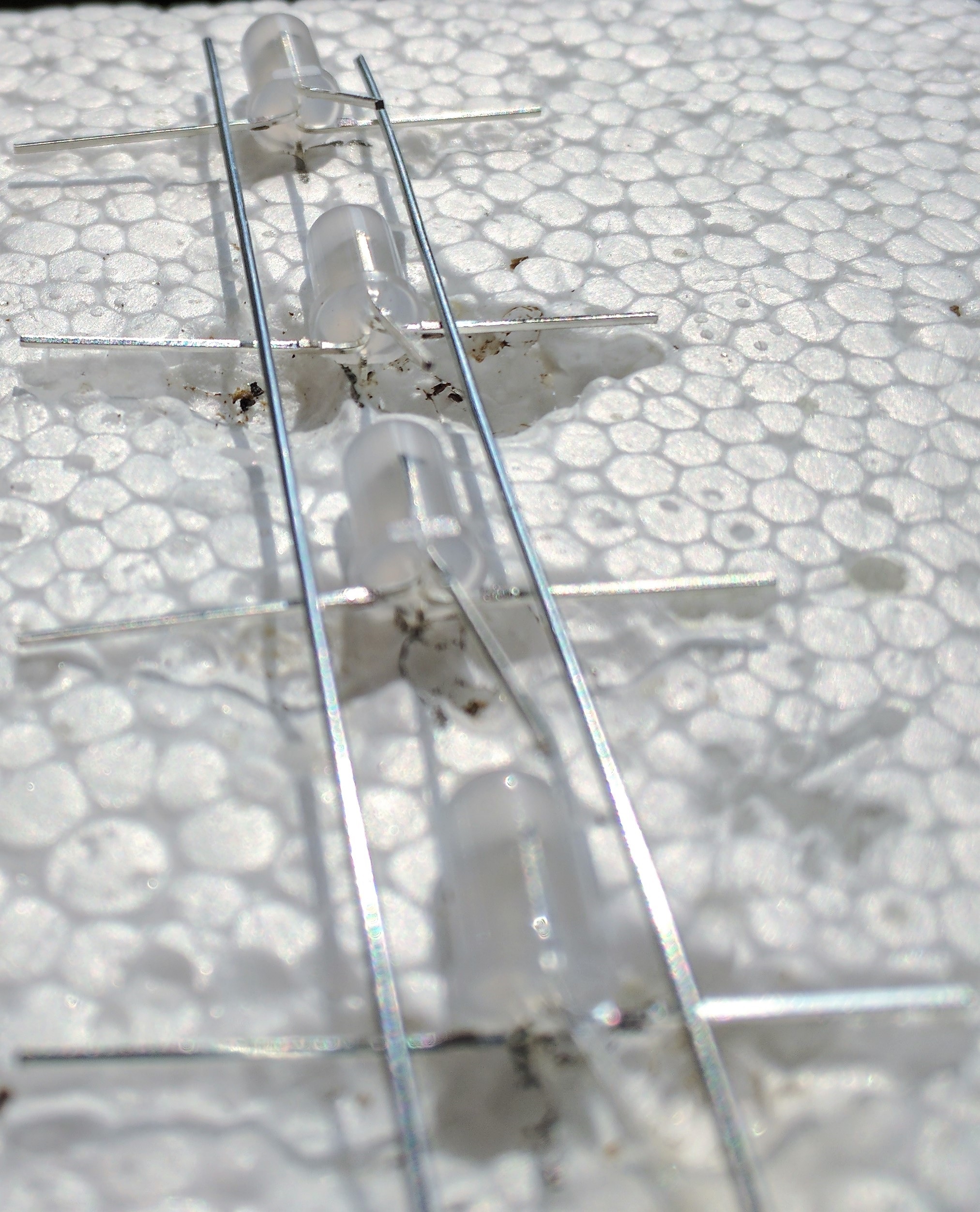
Next, the wire can be placed on top of the LEDs pins for +5V and GND. They need to be very close to the LEDs so that the layers can be 2cm apart later on:
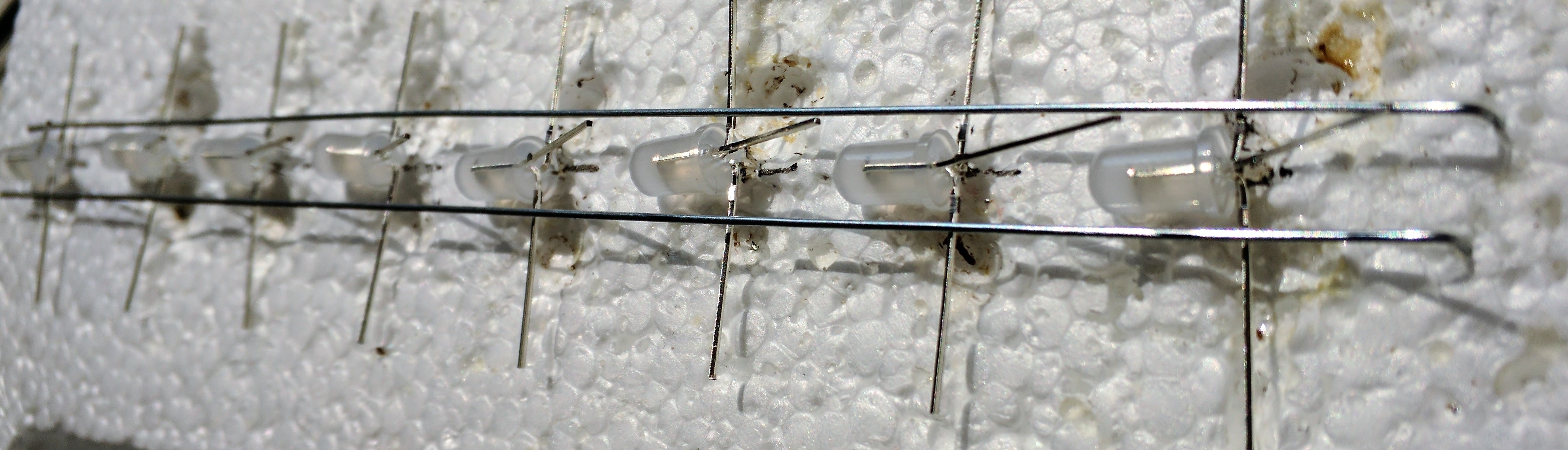
Note that the data pins go in alternating directions: the first LED has its Data In pin going down into the polystyrene, and the second has its Data Out pin going down.You can see this in the following photos. Note that the side of the LED with the flat edge is the side with the Data Out pin, so the order is: “Flat edge, Data Out, GND, +5V, Data In, (Round edge)”
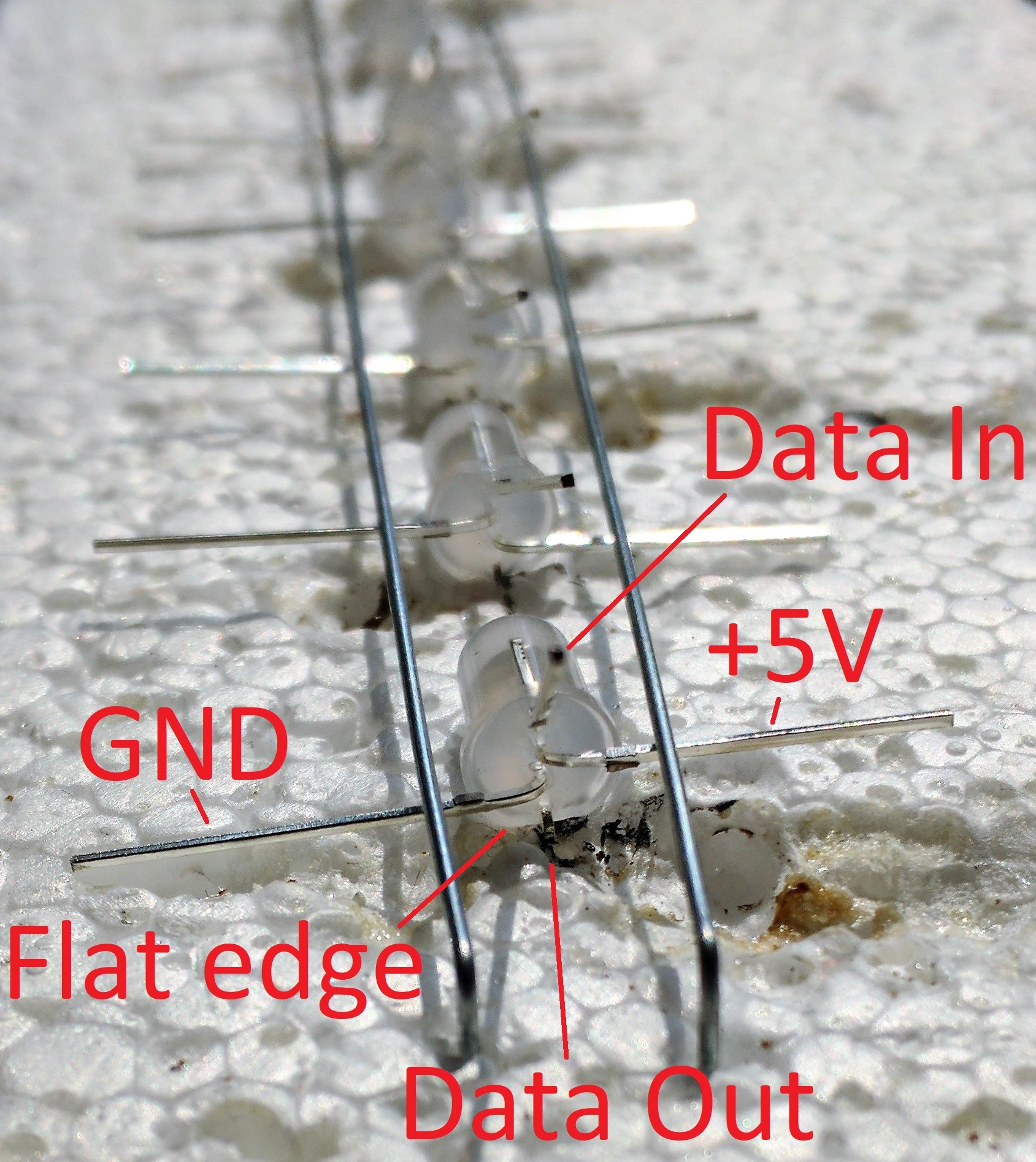
The reason that the LEDs alternate in direction is so that the data pins can all tie together into one continuous line going in one direction. This will be more clear when we solder 8 strips into a layer.
At this point, the strip is finished, and it needs testing because occasionally one of the colours on an LED won’t work. I did this by connecting the strip to a breadboard with a 5V power supply. Each LED draws around 60 milliamps at full brightness, meaning that a strip can draw 480mA, so a good USB power supply should be enough. To test the LEDs, I moved the data cable between the LEDs’ Data In pins while running a test program. The test program is a very simple one that cycles between red, green, and blue every half-second (it ran on a Raspberry Pi, with a USB cable connected to an Arduino Nano that sent the data signal).
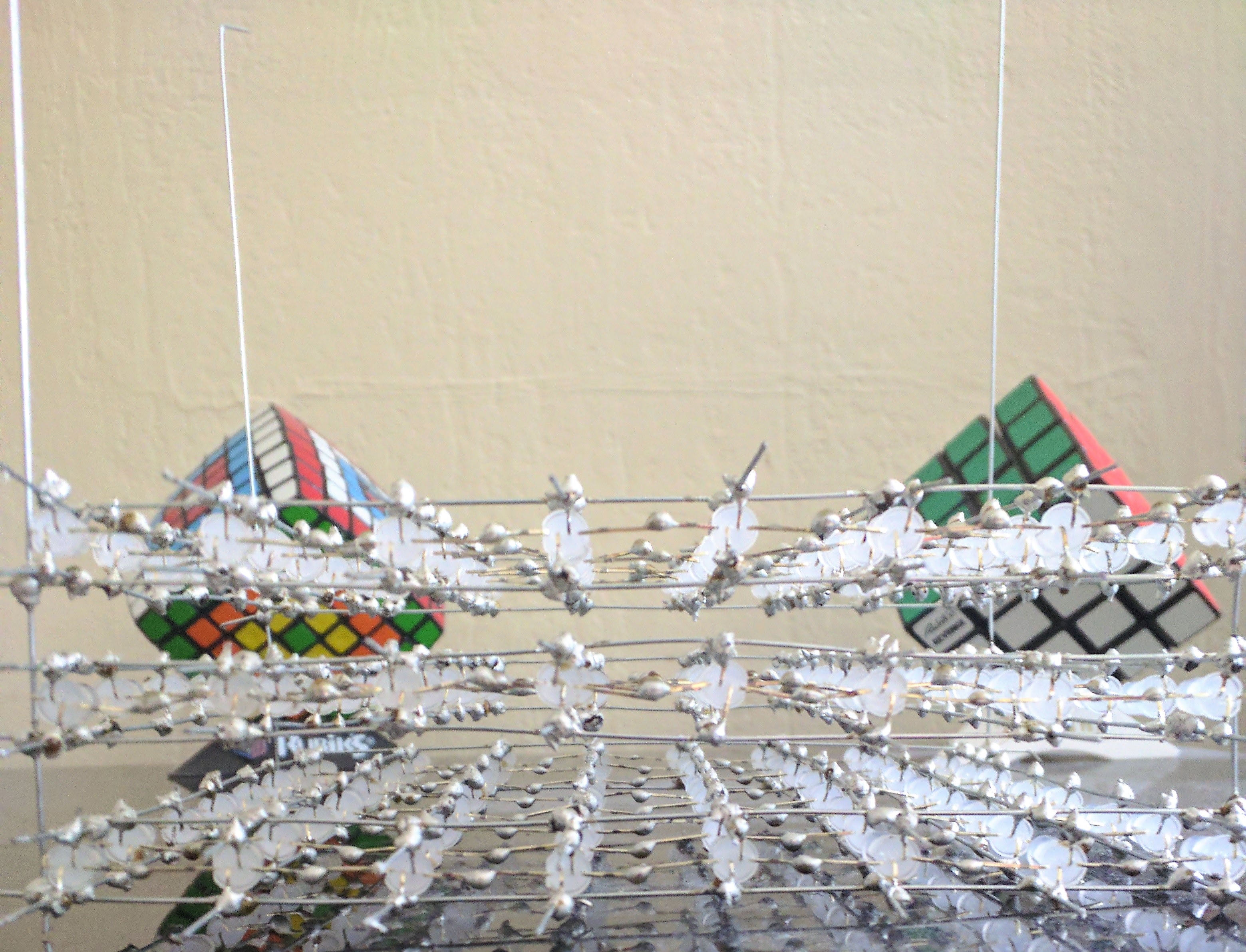
Here’s a photo of an old version being tested (this was when I was originally using 4cm gaps between LEDs):
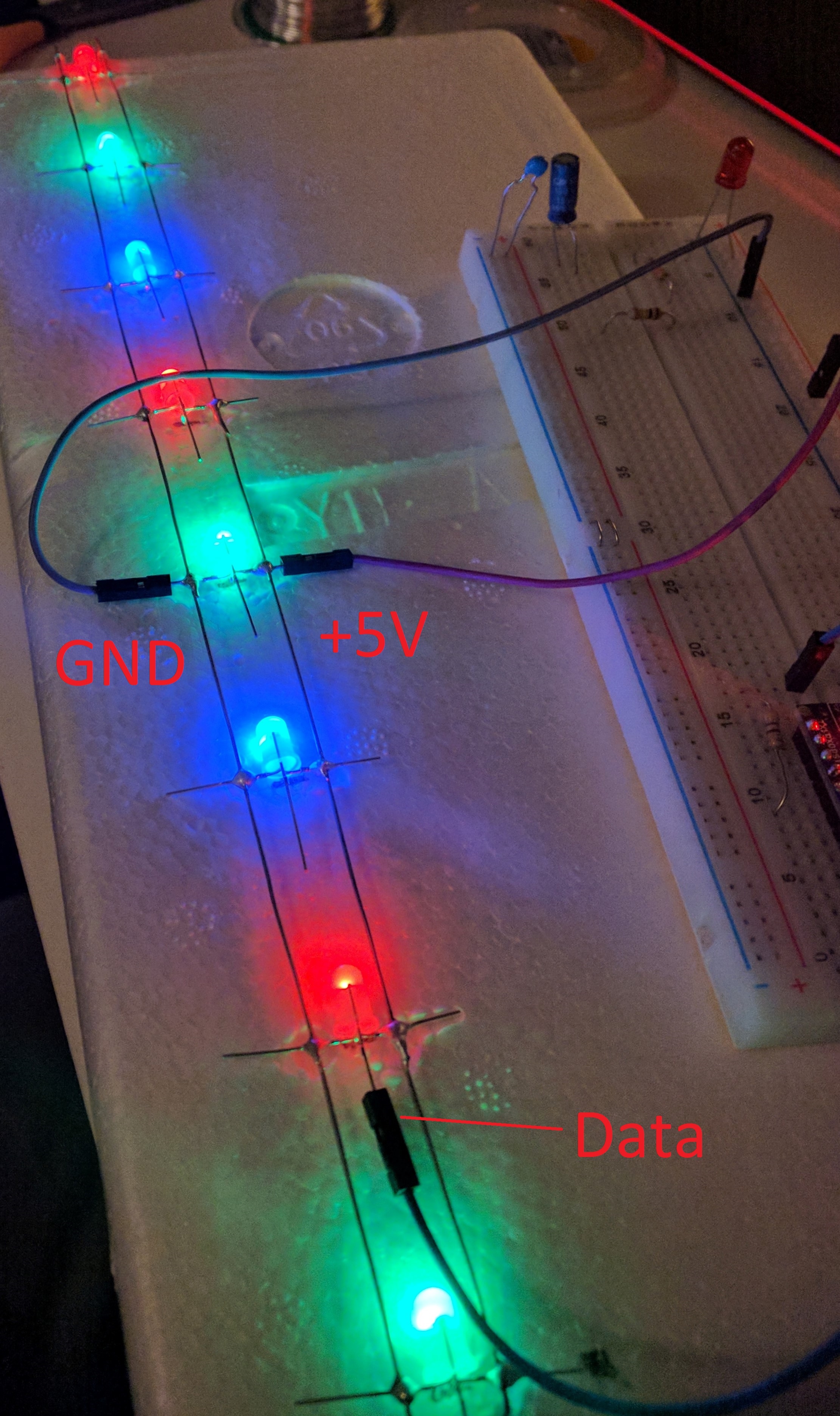
Note that the LEDs hold their colour when the data cable is not connected, so I’ve set them to an RGB pattern by disconnecting the data cable from each at the right time.
A layer
Once we have 8 strips, we can solder them together to make a layer. Here’s a diagram of how they fit together:
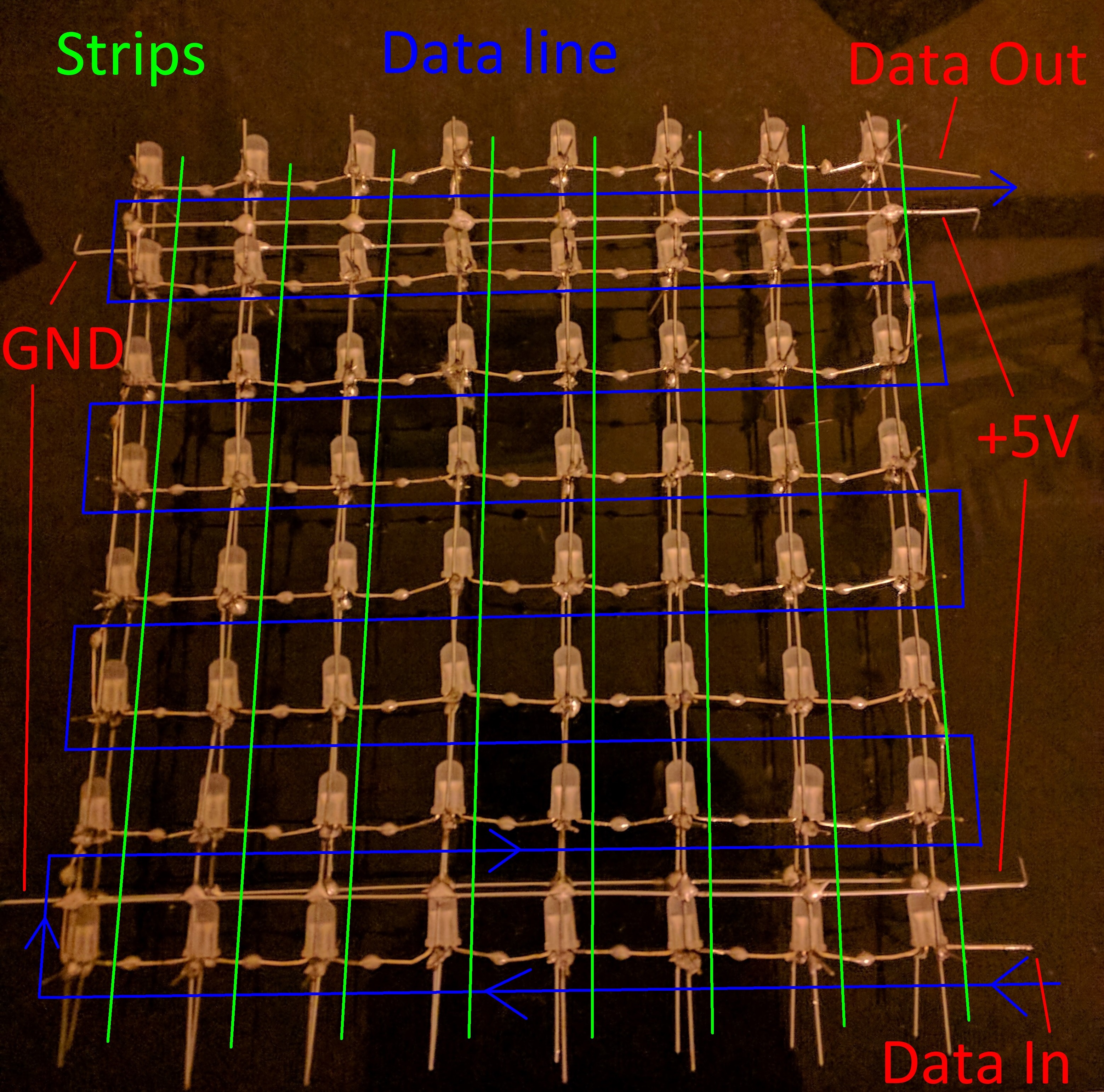
This requires careful alignment to make sure each strip is exactly 2cm from its neighbours all along its length.
- Use the uncut ends of the GND or +5V pins to stick each strip into the polystyrene. They should all be the same way around, so let’s assume all of the GND pins are facing down. It may take a lot of adjustments and careful measurements to ensure that the 2cm gap is maintained between all of the strips.
- Take four more straightened 16cm pieces of wire (with 90 degree kinks at the ends), and lay two of them across the top of the strips, connecting all of the +5V lines. There should be one half-way between the 1st and 2nd LEDs, and another half-way between the 7th and 8th LEDs. When positioning these pieces of wire, make sure that the end with the 90 degree kink is always on the right hand side, and as far away from the LEDs as possible while allowing all 8 joints to be soldered. This will give us some extra wire to work with when we are soldering the layers together later on.
- Solder the two pieces of wire down to the strips, making sure to measure the 2cm intervals after every joint. Once this is done, all 8 strips should be attached on the +5V side.
- Pull the layer out of the polystyrene and flip it over to do the other two pieces of wire, which will connect the GND lines.
At this point, the layer will have a common +5V plane and a common GND plane, but the data line will not be connected. - To connect the data line, bend the pins into the right positions as shown in the diagram above, and then use some wire cutters to trim each pair (that need to be connected) to length. It’s easiest to trim both of the pair at the same time. After all of them have been trimmed, they can all be soldered together, which completes the first layer.
On alternating layers, the strips need to be made with the data pins going in the opposite direction. This allows the data line to be reversed for the 2nd, 4th, 6th, and 8th layers, which ensures that the signal can go through them after it gets to the end of the 1st, 3rd, 5th, and 7th layers.
Once a layer is finished, it can be tested. Each layer contains 64 LEDs and each LED draws a maximum of 60mA, so the power supply for the test needs to supply 3.84A at 5V. One good test program for a layer is to draw a moving line of colour through the LEDs.
A cube
Once you have 8 layers, they can be connected together into a cube.
But first, they need trimming so that the +5V and GND pins do not interfere with the other layers:
To put the layers together:
- Decide which direction you want the layers to connect together in. (I forgot to do this, accidentally connected them from right to left, and had to flip the direction of the layers in software afterwards, because it was the opposite of my 4x4x4 cube.)
- Line up the layers in some polystyrene in approximate positions (they don’t need to be accurate yet). The layers should alternate in data signal direction, so that odd layers have their signal going upwards and even ones go downwards.
- Put four new pieces of straightened 16cm wire along the GND and +5V lines that are sticking out of the sides. These four wires should be as close to the LEDs as possible without touching any other wires (make sure they’re not too close to the data lines).
- The four lines can then be soldered to the first layer. It may be easier to remove the layers from the polystyrene before soldering the second layer, because the alignment is very difficult to get right at this stage, and it can be easier to solder each joint separately.
- Solder the rest of the layers onto these four lines, being very careful that they are connected at 2cm intervals, and that the layers are aligned horizontally and vertically.
- Solder the Data Out pin at the top of every odd layer to the Data In pin at the top of the next even layer. This will produce four sets of two layers that can be controlled independently. The inputs to each of these four pairs of layers will come from four pins on the microcontroller.
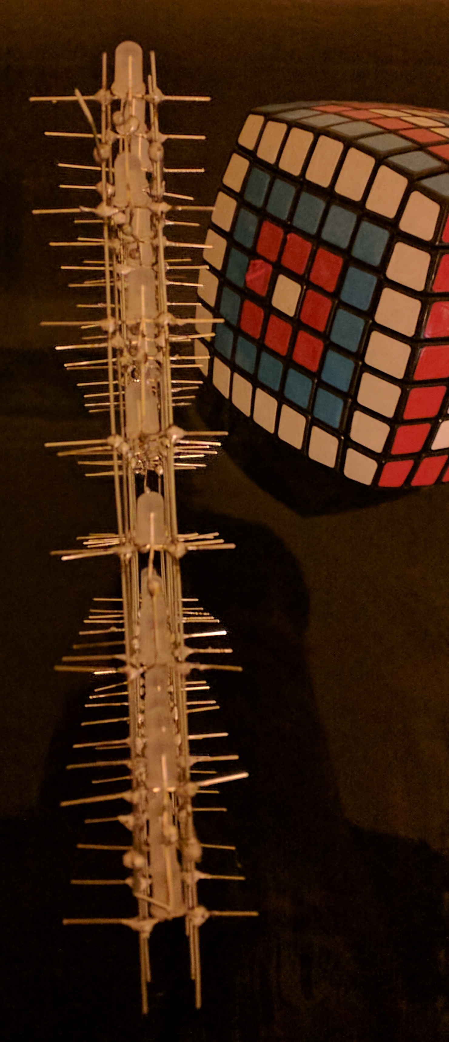
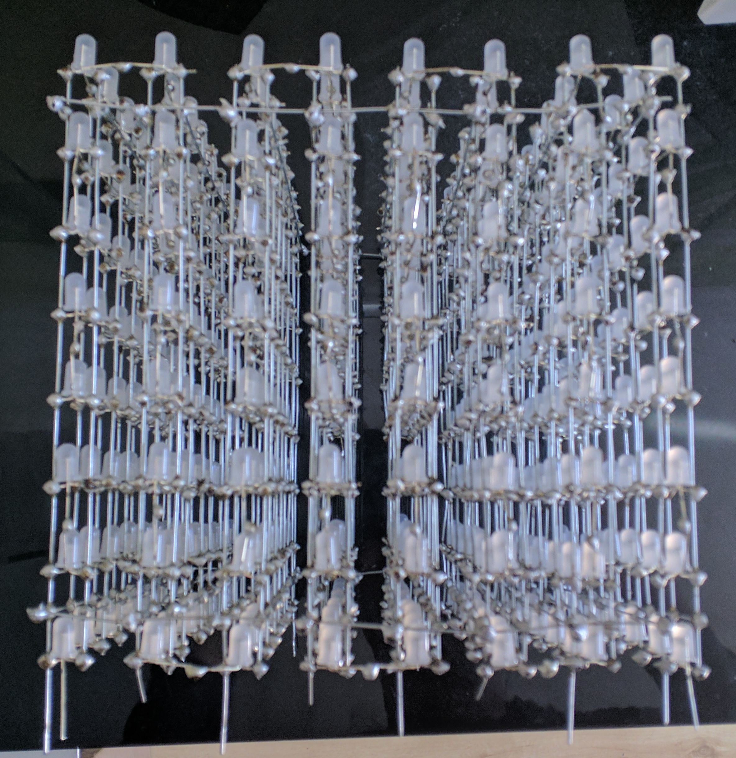
Here’s a cube with only three layers soldered on:
It’s important that two adjacent layers don’t touch, because one layer’s +5V plane is very close to the next layer’s GND plane.
Here’s the full cube after soldering:
Powering the Cube
At this stage, you should have a single cube of 512 RGB LEDs with a common ground and +5V line. However, this cube can draw up to (512 x 60mA =) 30.72 Amps! It will not turn on with a power supply that can’t supply a large current. Additionally, the wire connecting the LEDs together is fairly thin and probably won’t support a full 30.72A of current without heating up a lot. So to turn this on, we need some way to distribute a lot of power around the cube.
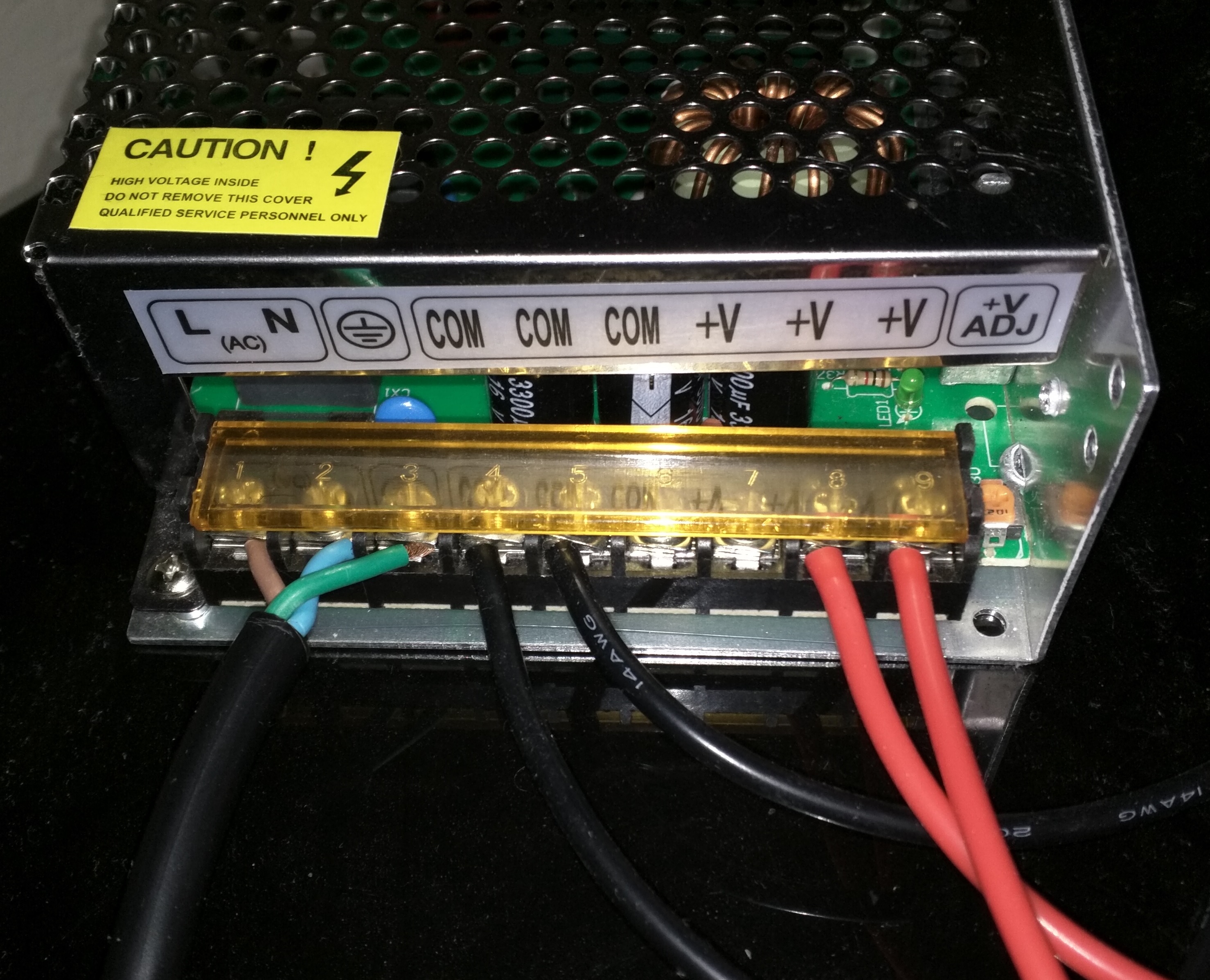
The way I decided to do this was to buy two thick pieces of copper wire (one with red insulation, one with black) with enough conductance to support the whole cube. I then stripped the insulation from the middle(-ish) of each piece of wire, and soldered it along the bottom +5V and GND lines connecting the layers together.
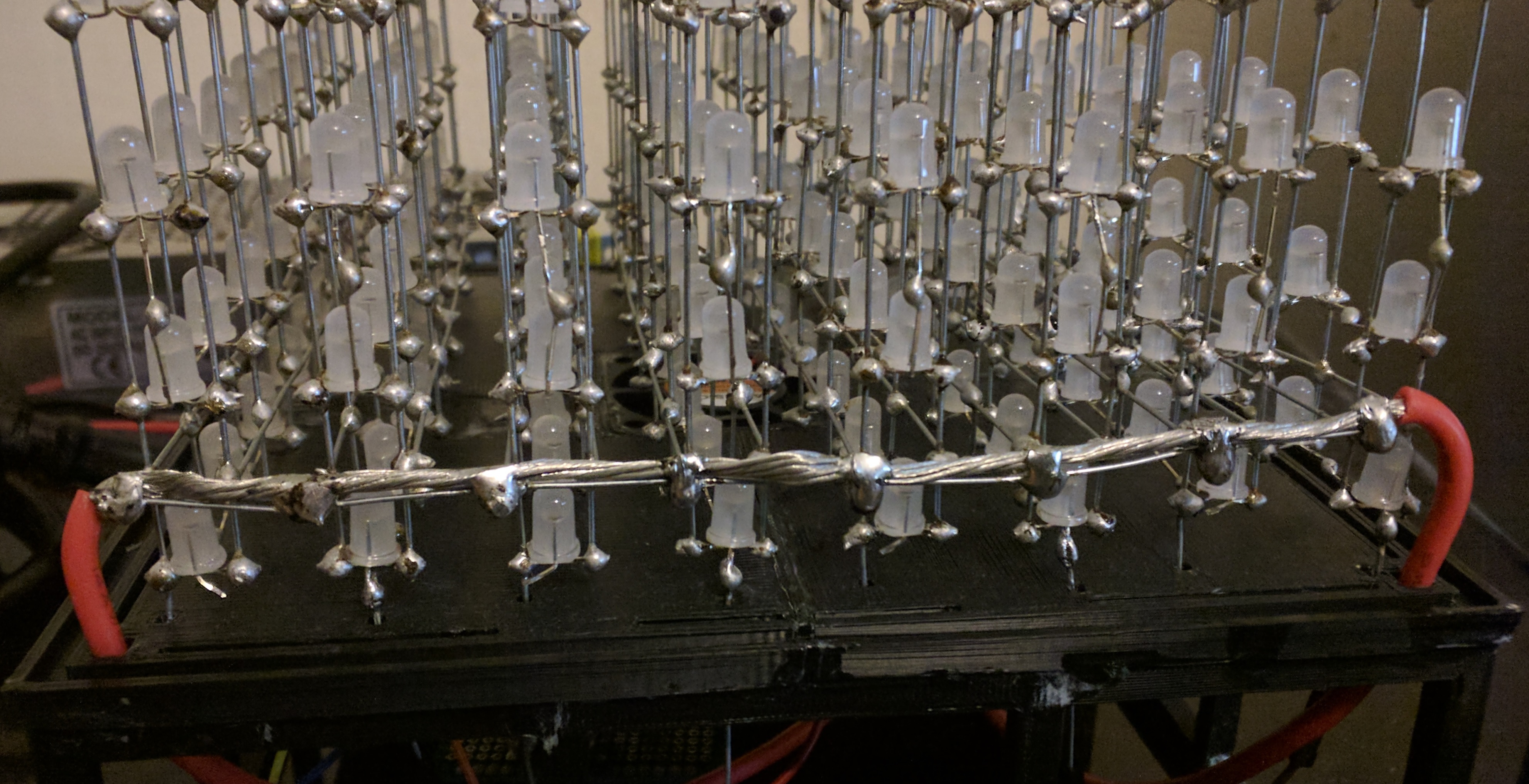
I then collected the two ends of each wire and secured them into the terminals on the power supply (I measured my wires so they each had the right amount of slack to reach it). My power supply is a brick that supplies 40A at 5V and has three terminals for +5V and three for GND, so it can cope with the power and logistical requirements.
Controlling the Cube
The cube isn’t very interesting if all it does is show the blue colour that the LEDs default to. The microcontroller attached to it is what allows it to display more interesting patterns, however the microcontroller I use is also fairly simple: it just connects to my server using a wireless internet connection and displays whatever the server tells it to. This allowed me to make a web interface and control the cube from my phone, but it does require a constant internet connection and can eat up some data (at 20 frames per second, it uses around 30 KB/s).
Client hardware
The client I use for the cube is an ESP-12E module, which has an embedded wireless chip and a 160Mhz processor.
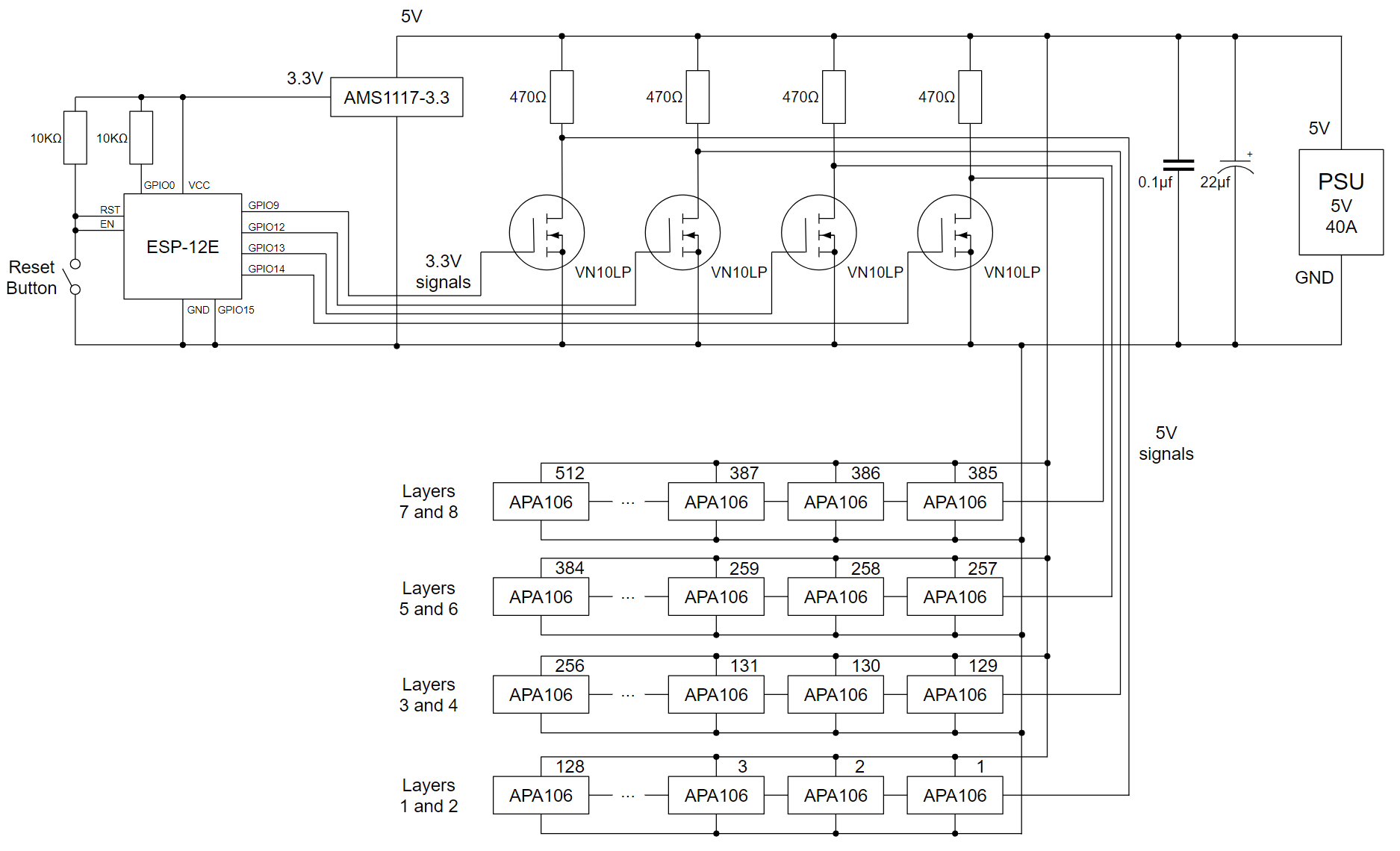
As I mentioned in my previous post, the timing for the APA106 LEDs is fairly precise, and needs a signal pulse every 1710 nanoseconds (of either 350ns for a zero bit, or 1360ns for a one bit). This requires some circuitry that can cope with fast changes without suffering from interference.
Annoyingly, the ESP-12E works at 3.3V rather than 5V, so I had to use a voltage regulator to convert the cube’s 5V power supply down to 3.3V first, and then use some transistors to pull the signal wires it outputs back up to a 5V signal (which actually inverts the signal at the same time, so the code has to send 0 when it means 1 and vice versa).
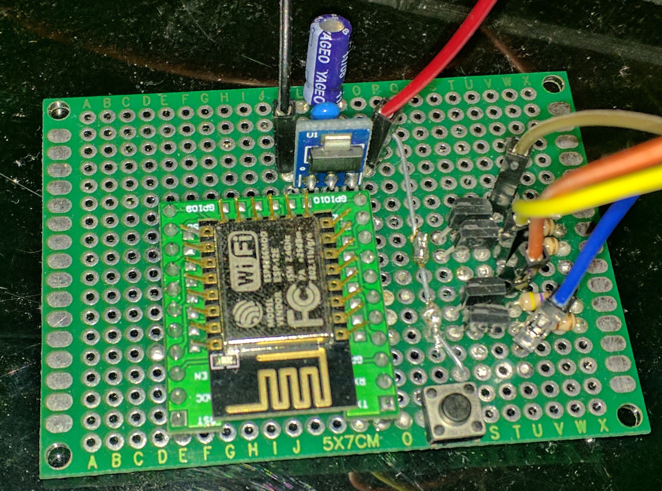
To make sure power supply is smooth and doesn’t suffer from any interference, I have both a ceramic capacitor and an electrolytic capacitor in parallel across it.
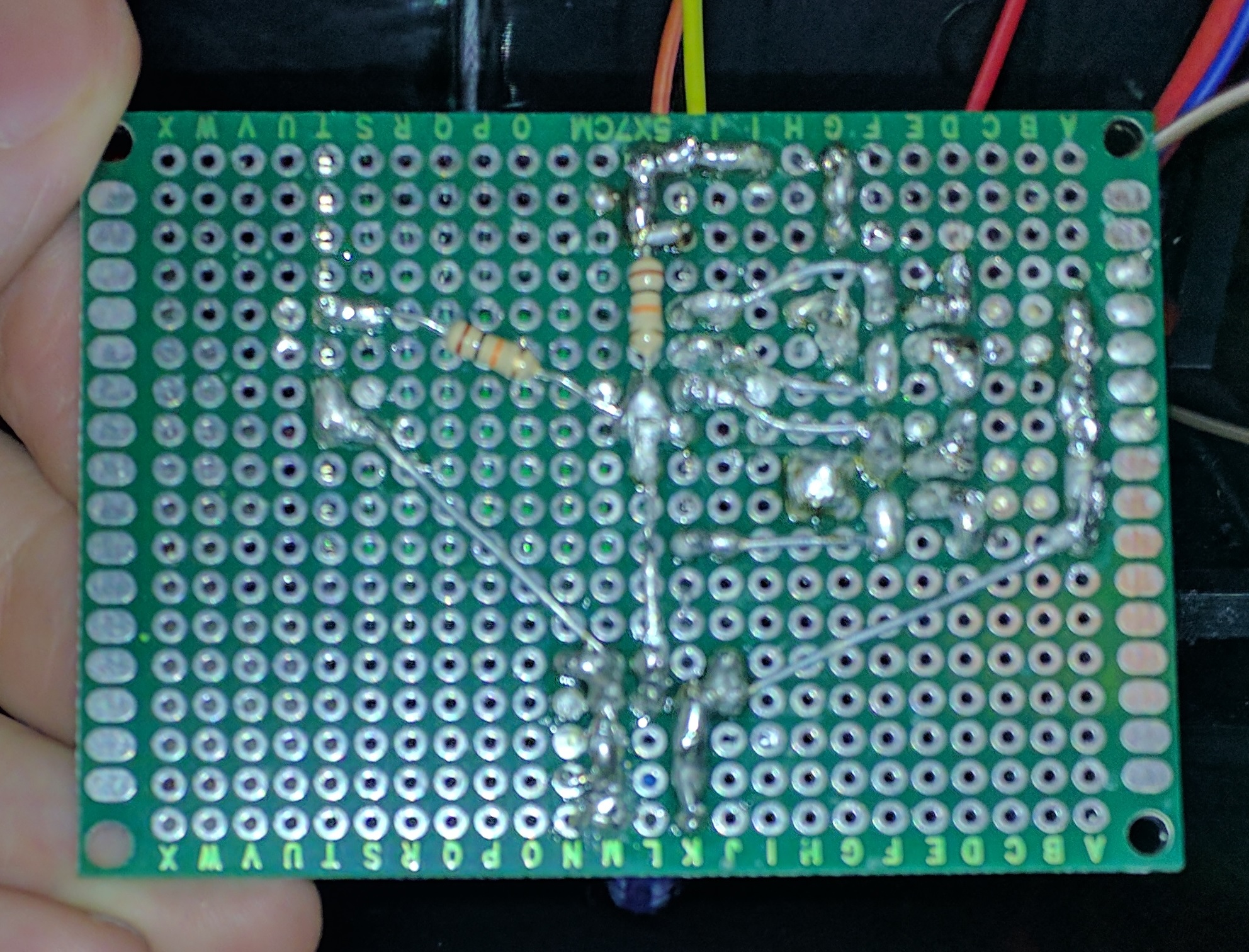
To convert the signal from the four data-out pins from 3.3V to 5V, I’m using four n-channel MOSFETs and four 470Ω pull-up resistors. Here’s the circuit diagram (click to zoom):
Client software
The ESP-12E (which uses the ESP8266 chipset) can be programmed as an Arduino device. While it doesn’t support the instruction timing that I used in the Arduino Nano program, it is fast enough that it can count the clock cycles itself. It also has enough spare cycles to calculate four different output signals at once, which decreases the time required to update the cube by a factor of 4, from ~21ms to ~5.25ms. It takes this long because there are 512 LEDs to update, each of them need 24 bits of colour data, and each bit takes 1710 nanoseconds to send: 512 x 24 x 1710ns = 21,012,480ns ~= 21ms. Since interrupts must be disabled while sending the signal to the cube, pausing for 5.25ms is much more feasible, especially when we want to update at 20-30 frames per second and we’re waiting for data from the wireless network at the same time.
There are some really useful Arduino libraries for WiFi management. The one I’m using will auto-connect to the last network it connected to, but if it fails for some reason or can’t connect to the server it will start up its own network with a captive portal that lets you scan for networks and enter the password to one, after which it will connect to that network and continue from there.
The full client code is here:
https://github.com/abryant/LED-Cube/tree/master/arduino
Server software
The server is a multithreaded Python HTTP server. When a request comes in from the cube, it registers that the cube exists and starts a controller that keeps the connection open indefinitely to send frames to. The web interface sends commands via POST requests, and when one comes in the controller responds by changing what the cube is doing, for example by changing the current visual displaying on the cube. When a non-interactive visual is running, the controller just gets the next frame 20 times per second (or at whatever speed the controller has been set to). Interactive visuals are handled differently, and can respond to other POST requests from the web interface.
The visuals themselves are python generator functions (similar to an infinite iterator, but much easier to write) that yield Cube objects or lists of colours. A Cube object is a 3D array of colours with some utility functions that let the visuals do interesting things. The visuals themselves can be quite short pieces of code, for example “Layers” is less than 30 lines, and more complex ones like “Faces” and “Snakes” are less than 100 lines of code. “Starfield” has about 5 lines of actual non-boilerplate code.
The visuals can also be chained together in sequences, using some generator utilities (which is what’s happening in the video above). Whenever a generator yields a boolean value, the generator utilities treat it as a break point and have the option of moving on to another visual, or doing something else.
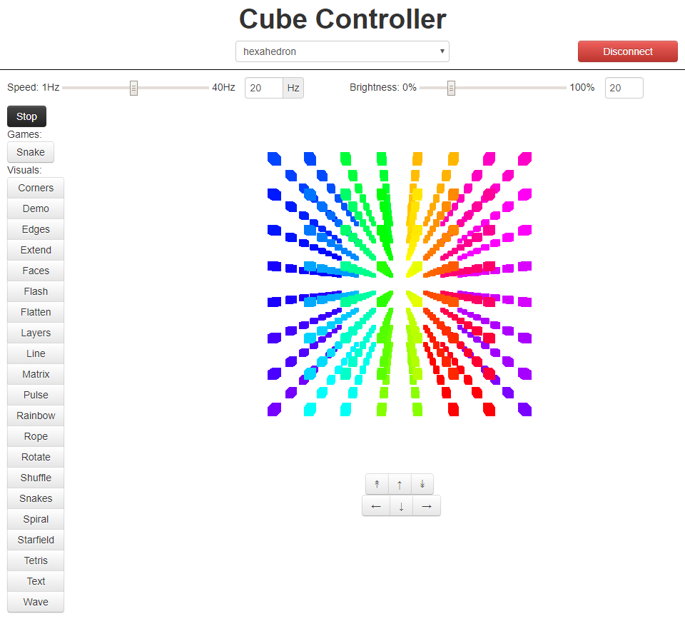
The server also sends the current state of the cube to any listening instances of the web interface, which then draws it on screen:
This cube was a lot of fun to make, and I’m still experimenting and improving it with software (e.g. new visuals) and hardware (e.g. ways to cool the LEDs when they’re at full brightness). It taught me about soldering (I hadn’t soldered for about a decade), building circuits, Arduino programming, Python web servers and generators, WebGL, and probably lots of other things.
Thanks to everyone who helped me, and to those who came up with ideas for visuals to display on it. Special thanks to my grandfather James M. Bryant without whose help I wouldn’t have known about APA106 LEDs, the ESP-12E, or the various bits of electronics I needed to put the whole thing together.
I have a few ideas for new visuals, but I’m always interested in more – feel free to send me ideas, or even better, write code for them and send it to me!